This post is a part of a series about the TouchBerry ModbusRTU autoflow issue and how have I resolved it. Other posts of the series can be found under the touchberry tag. Note that newer posts might contain more recent information.
Throughout the series I have been investigating the mysterious UPS shield that can be ordered as a highest configuration of TouchBerry 10 from IndustrialShields (links in the previous posts).
The documentation for this panel sadly does not contain anything about the RS-485 interface, nor ModbusRTU that uses it. The first documentation was available as a support email, specifically mentioning the pinout of the 40 pin Raspberry Pi 4 header, powering the panel:
| Fn | Descr. | # | # | Descr. | Fn |
|---|---|---|---|---|---|
| NC | 7 | 8 | GPIO14 | TXD | |
| NC | 9 | 10 | GPIO15 | RXD | |
| RE | GPIO17 | 11 | 12 | NC | |
| DE | GPIO27 | 13 | 14 | GND |
What I have repeatedly found that this is in fact not the case, instead of GPIO17 driving the RE pin (pin number 2) of the obscure UTRS485G part and GPIO27 driving the DE pin (pin number 3), the GPIO17 does nothing (as far as I can tell) and GPIO27 drives both RE and DE.
When trying to send some command from the TouchBerry to a ModbusRTU device,
for instance by switching a coil using mbpoll:
mbpoll -a 2 -b 9600 -t 0 -P none /dev/ttyS0 1
The following error can be seen, even though the device sets the coil.
Write discrete output (coil) failed: Connection timed out
The reason is obvious - the response from the device did not reach the Pi. Here's a further proof of what's happening with the UTRS485G, having the GPIO27 pulled HIGH all the time:
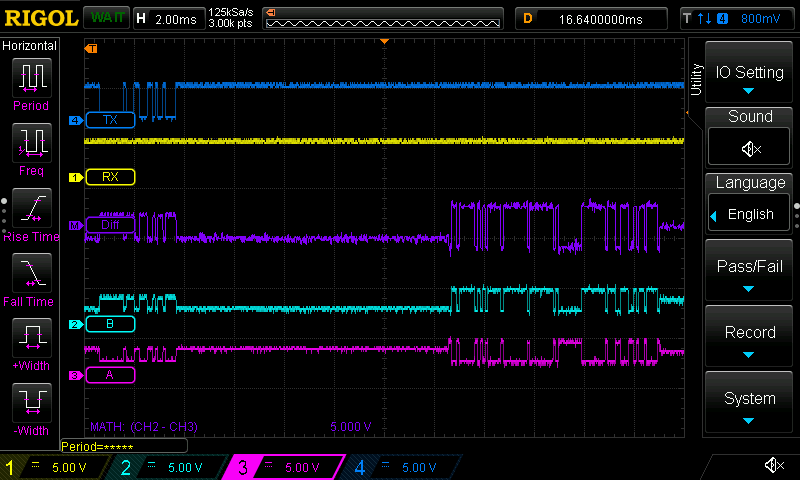
The RX has no transmission whatsoever, because the UTRS485G awaits that both pins 2 and 3 (RE and DE) would be pulled LOW after the transmission to reverse the direction. It is of course achievable with the script from the part 1 or similar, but it is a big hassle to deal with. I could later confirm that the pins 2 and 3 on the IC are in fact correctly interconnected on the PCB when doing the part replacement, as can be seen in the combined picture below:
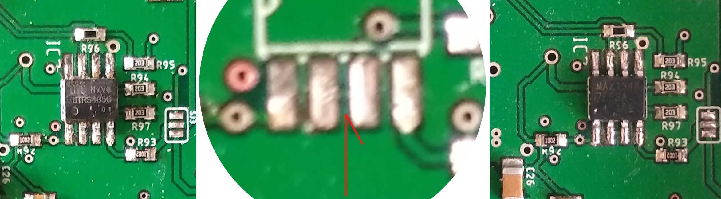
The replacement was a Great Success. The MAX13487E has an automatic direction control, or autoflow for short - the feature I was hoping I could achieve either by software (via RTS0 pin, but since it is on the GPIO17 and not GPIO27, it is impossible, not to mention it is a reverse polarity anyway) or by some hardware change. Here's how the scope rendered the test ModbusRTU communication of switching the coil after the IC was replaced:
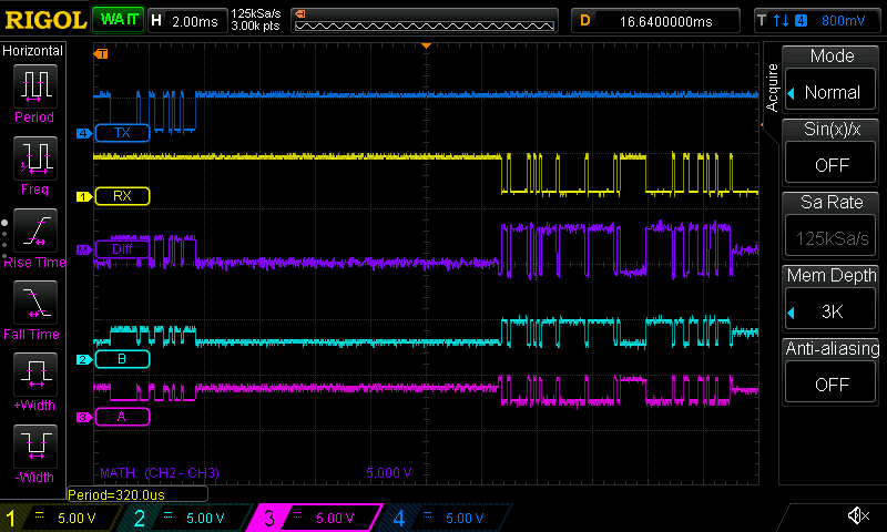
Now the RX has the response from the device. Both scope screenshots omit
the pins 2 and 3, but with the MAX13487E, they are constantly pulled HIGH.
To achieve that from the startup, I could put a pull-up resistor on the
GPIO27 or I could probably also enable the pull-up resistor in the Pi
on that pin (did not try yet). I have however found another, maybe a little
bit more portable way
here.
In short, edit /boot/config.txt and add to the bottom:
dtoverlay=gpio-poweroff,gpiopin=27,active_low
This pulls the GPIO27 HIGH as soon as the TouchBerry boots, making
ModbusRTU calls in conjunction with MAX13487E a breeze, meaning the Pi also
gets the response from the device. With the above setting, there's no need
to manually change any pin state or function, whatsoever. Since the
/boot/config.txt is a standard edit entry point for many using Raspberry,
it is probably the best way to store this functionality.
RS-485 termination
Note that there is no 120R termination resistor on the side of the UPS
shield, so when hooked to the device that also does not have any, and there
is neither one present on the cable between the A and B lines, the response
from the mbpoll can look like this:
Write discrete output (coil) failed: Response not from requested slave
Inserting the aforementioned 120R between the A and B solves the problem and the response now reports the following all the time:
Written 1 references.
Generally, the person making the RS-485 connection is responsible to provide the proper bias and termination resistors, so this is in fact not the problem with UPS shield on TouchBerry 10 per se, it is just a thing to have in mind.