Continuing my, now semi-regular work on the cabinet wiring, I have found myself in a curious situation. The datasheet for the product contained the following schematic:
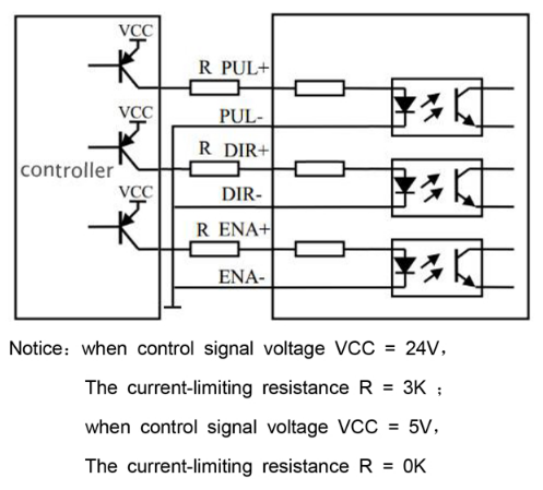
The schematic demonstrates the recommended wiring between the controller, in this instance a PLC and the device itself. I will refer to it as device, but a keen eye can also catch the input labels, recognizing the device to actually be a stepper driver. I have started writing about stepper motors here and then more recently here, but this post is more general and can be translated to other devices with inputs as well.
The schematic specifically discusses the device inputs in a common cathode wiring configuration, in the industrial automation jargon known more loosely simply as "PNP". Note that there is nothing wrong with the schematic or the wiring itself.
Resistors in a wiring cabinet
Most things related to wiring cabinets and PLCs tend to work around the nominal arbitrary value of 24 VDC. The 24VDC applies the supply voltage as well as to discrete signals. From the schematic above, it its clear however, that the device was designed to work with the 5V signals as well. These are historically common for the TTL logic level electronics.
The description under the schematic shows, that the internal current-limiting resistor for the optocouplers inside the device is sufficiently high for the 5V inputs. Yet here's the catch. The internal resistors might not be sufficient when the signal levels are higher. For the significantly higher voltages, 24 V specifically, the description recommends an additional 3K series resistor, otherwise the optocoupler's diode could burn, permanently damaging the input.
The value of internal resistor
Without any measurements, lets calculate the most probable value of the used internal resistor. Keep in mind that these values are ballpark values. Most common optocouplers operate safely with the diode current of 2.5mA to around 25mA and are able to safely sustain short peaks of around 50mA, give or take.
Let's assume around 10mA flows through the diode with the 5V input signal. What is the internal resistor value?
5 V / 0.010 A = 500 ohm
Calculating the actual resistor value range for the 5V signals would bring us to the following table, adjusted for the resistor standard values:
| ohms | current | description |
|---|---|---|
| 220 | 22.73 mA | minimal resistor |
| 470 | 10.64 mA | safe value |
| 1k | 5.00 mA | 3.3V included |
| 2k2 | 2.78 mA | maximal resistor |
If the device is capable of using a 3.3 V signals, although the datasheet does not mention it, the maximal internal resistor value is more limited:
3.3 V / 0.0025 A = 1320 ohm
Standard value available is 1k2 but 1k is far more likely. With the above in mind, it is probably safe to assume that the internal resistor's values is somewhere in the range from 220 ohms to 1k, possibly, but not likely up to 2k2.
24 V signals
Let's calculate what would happen when the external resistor is using when 24 V signals are applied:
| ohms | current | description |
|---|---|---|
| 220 | 109.09 mA | diode fried |
| 470 | 51.06 mA | diode in danger |
| 1k | 24.00 mA | diode reaching its limits |
| 2k2 | 10.91 mA | diode safe |
It is very likely that the sane designer had chosen a value of 1k for the internal resistor, as it makes it safe to use for the voltages from 3.3 V to a little above 24 V and everything in between, including 5 V and 12 V. So why is the 3k external resistor recommended for 24 V signals?
The 3k external resistor mystery
Recalculating the above table for the 24 V signals with the external 3k resistor we get these values:
| internal R | external R | ohms | current |
|---|---|---|---|
| 220 | 3k | 3220 | 7.45 mA |
| 470 | 3k | 3470 | 6.91 mA |
| 1k | 3k | 4k | 6.00 mA |
| 2k2 | 3k | 5k2 | 4.62 mA |
No matter the internal resistor resistance, all the current values are well within the safe range.
We have the numbers, now what?
The numbers are nice, but there is more practical problem on hand. Where does one put a humble resistor in the wiring cabinet? There are also others asking this very question. The best solution I have found for making the cabinet documentation a breeze, while simultaneously making that same cabinet reproducible and repairable by others is to use WAGO 289-114 with 288-001 and 288-002. To save you from searching, it looks like this:
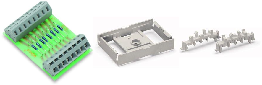
These three combined can be mounted on the DIN rail, which is almost a must for most wiring cabinets I have encountered. There are 8x resistors are the terminals to insert cables. The WAGO 236 terminals require a special lever tool to insert the wires, but it can be done with a flat screwdriver if really desperate, although it will leave visible marks on the terminals.
There is only single complain - the 289-114 contains resistors with the nominal value of 2k7, not the 3k recommended for our device. Will it make a difference? You probably know, but for the sake of completeness, here's the calculation:
| internal R | external R | ohms | current |
|---|---|---|---|
| 220 | 2k7 | 2920 | 8.22 mA |
| 470 | 2k7 | 3170 | 7.57 mA |
| 1k | 2k7 | 3k7 | 6.49 mA |
| 2k2 | 2k7 | 4k9 | 4.90 mA |
So will it work with 2k7 instead of 3k external resistors using 24 V signals? Absolutely.
This is a 97th post of #100daystooffload.